360 Bird's Eye View Camera Stitching Operation Manual
Detailed Operation Guide & Troubleshooting
1. Preparation Before Operation
1.1 Tool List
- Calibration Cloth for Stitching: 1 set, including 2 large calibration cloths, 2 small calibration cloths (for image calibration positioning).
- Tape Measures: 3-4 pieces, at least 2 of which should be longer than 5m (for measuring vehicle parameters and calibration cloth placement distances).
2. Detailed Operation Steps
12.1 Step 1: Enter 360 Surround View System
Find and click the "360 Surround View" entry on the device's main interface to enter the surround view control interface.
Interface Display Content:
- Display Mode: Supports switching between 2D display and 3D display.
- View Partition: The interface is divided into four camera view areas: "Front View", "Rear View", "Left View", "Right View".
- Function Buttons: There is a "Settings" button at the bottom or side of the interface (core operation entry, needed for subsequent steps).
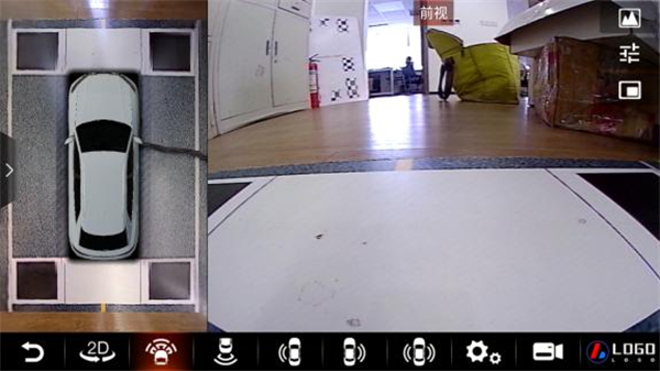
Figure 1: 2D Display Mode
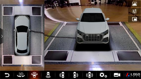
Figure 2: 3D Display Mode
22.2 Step 2: Enter System Settings Interface
In the 360 Surround View interface, click the "Settings" button to enter the main settings interface.
Settings Interface Contains the Following Core Options:
- Vehicle Model Settings: Adjust vehicle model color, scaling ratio, black edge removal (ON/OFF), 2D rear view scale line (ON/OFF), etc.
- View Settings: Supports display mode switching such as "Left Split Screen".
- Original Vehicle Settings: Match basic vehicle information (such as sedan, SUV, MPV, Mercedes-Benz GLE, etc.).
- Recording Settings: Manage recording related parameters (not core to stitching, not expanded here).
- Remote Service: Device remote functions (not core to stitching, not expanded here).
- Parameter Management: Core entry for stitching debugging, used to enter stitching settings, parameter import/export, restore defaults, etc.
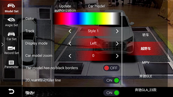
Figure 3: System Settings Interface
32.3 Step 3: Enter Stitching Parameter Management Interface
In the settings interface, click the "Parameter Management" option to enter the parameter management interface.
Interface Core Functions:
- Stitching: Click to enter the "Calibration Cloth Selection and Stitching Method Settings" interface (key entry for stitching operations).
- Import Parameters: Import saved stitching parameters (suitable for secondary debugging of the same vehicle model).
- Export Parameters: Save the current debugged stitching parameters (for backup).
- Restore Defaults: Reset to system default stitching parameters (suitable when parameters are confused).
- Activation Information: View device activation status (not core to stitching).
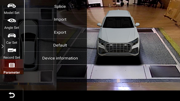
Figure 4: Parameter Management Interface
42.4 Step 4: Select Stitching Method and Calibration Cloth Type
After clicking the "Stitching" option, enter the "Calibration Cloth Selection and Stitching Method" interface, where two selections need to be completed:
2.4.1 Select Stitching Method (Choose One)
| Stitching Method | Applicable Scenarios | Operation Points |
|---|---|---|
| Lens-Free Stitching | No need for precise camera model matching, simpler operation | No need to select camera model, directly enter calibration cloth selection |
| Lens Selection Stitching | Need to precisely match the installed camera model (ensure stitching accuracy) | Need to select the model corresponding to the actually installed camera in subsequent steps |
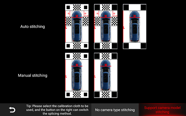
Figure 5: Stitching Methods Selection
2.4.2 Select Stitching Mode (Choose One)
- Automatic Stitching: The system automatically recognizes the calibration cloth and completes basic calibration (recommended for beginners, high efficiency).
- Manual Stitching: Need to manually position key points of the calibration cloth (suitable when automatic stitching effect is poor).
2.4.3 Select Calibration Cloth (Core)
- For lens-free stitching: Priority selection of "Large Black Block Calibration Cloth" (recommended by documentation, higher calibration accuracy), left and right calibration cloths can be omitted or used only for reference.
- For lens selection stitching: In manual calibration scenarios, left and right calibration cloths do not need to be placed, only front/rear large calibration cloths are needed.
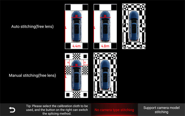
Figure 6: Calibration Cloth Selection Interface
52.5 Step 5: Place Calibration Cloths (Critical Step, Affects Stitching Accuracy)
After completing the stitching method selection, place the calibration cloths and tape measures according to the following requirements to ensure the basis for image calibration:
2.5.1 Calibration Cloth Placement Rules (Taking "Lens-Free + Automatic Stitching + Large Black Block Calibration Cloth" as an Example)
- Front/Rear Large Calibration Cloth Placement:
- Position: Place 1 large calibration cloth in the area corresponding to the front camera, and 1 large calibration cloth in the area corresponding to the rear camera.
- Attitude: The large calibration cloth should be placed centrally and perpendicular to the vehicle body (ensure parallel to the vehicle body, can be assisted with tape measures for alignment).
- Distance: The distance from the front calibration cloth to the front of the vehicle and from the rear calibration cloth to the rear of the vehicle is based on "the screen can completely display the calibration cloth"; the closer the edge of the cloth is to the camera's visible range, the smaller the vehicle's blind spot.
- Tape Measure Placement:
- Take 2 tape measures with length > 5m, place them parallel to the ground along the front and rear directions of the vehicle body (assist in calibrating the parallelism between the vehicle body and the calibration cloth).
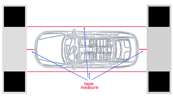
Figure 7: Calibration Cloth Placement Diagram
2.5.2 Camera Installation Requirements (Pre-check to Avoid Stitching Deviation)
- The camera image should be parallel to the vehicle body, with "just able to see the edge of the vehicle body" as the baseline.
- The installation angles of the left and right cameras should be as consistent as possible, and the "black squares" of the front/rear calibration cloths should be visible (ensuring key point recognition).
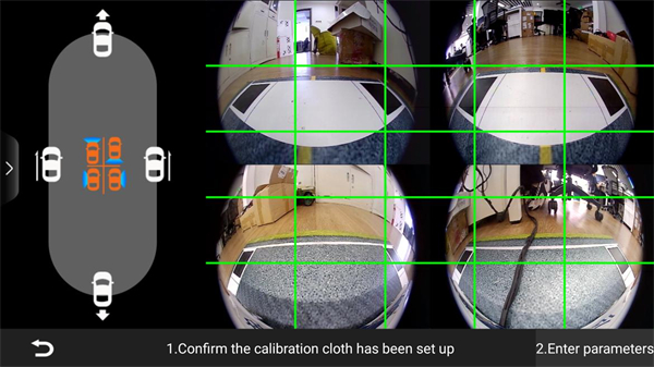
Figure 8: Camera Installation Requirements
62.6 Step 6: Input Vehicle Parameters (Required, Accuracy Affects Stitching Effect)
After placing the calibration cloths, click the "Enter Vehicle Parameters" button in the interface to enter the parameter input interface.
Required Parameter List (Unit: m, items with * are required, need to be actually measured with tape measure):
| Parameter Name | Measurement and Entry Points |
|---|---|
| Vehicle Length | Measure the distance between the farthest front and rear ends of the vehicle (such as the straight-line distance from the front to the rear) |
| Vehicle Width | Measure the distance at the widest point left and right of the vehicle (usually the distance between the outside of the rearview mirrors) |
| Vehicle Height | Measure the distance from the bottom of the vehicle to the highest point at the top |
| Wheelbase | Measure the distance from the center of the front wheel to the center of the rear wheel |
| Front Wheel Track | Measure the distance between the centers of the left and right front wheels |
| Rear Overhang | Measure the distance from the center of the rear wheel to the rear of the vehicle |
| Rearview Mirror - Front of Vehicle | Measure the distance from the outside of the rearview mirror to the frontmost part of the vehicle |
| Rear of Vehicle - Rear Calibration Cloth | Measure the straight-line distance from the rearmost part of the vehicle to the rear calibration cloth |
| Front of Vehicle - Front Calibration Cloth | Measure the straight-line distance from the frontmost part of the vehicle to the front calibration cloth |
| Front/Rear/Left/Right Camera Height | Measure the vertical distance from the center of the corresponding camera to the ground respectively |
Note: If using lens selection stitching: Need to additionally select "Lens Type" in the parameter input interface (must completely match the actually installed camera model, such as 6053_2239).
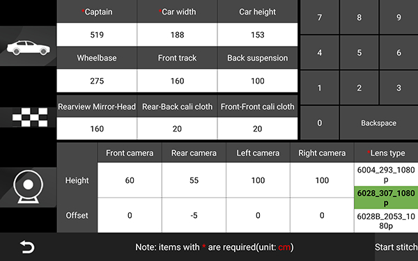
Figure 9: Vehicle Parameter Input Interface
After filling in the parameters, carefully check (avoid numerical errors), and after confirming there are no errors, click the "Start Stitching" button.
72.7 Step 7: Complete Stitching (Automatic + Manual Combination)
2.7.1 Automatic Stitching Process
- After clicking "Start Stitching", the system will automatically recognize the positions of the front/rear calibration cloths and complete basic image calibration.
- After automatic calibration is completed, the system will automatically enter the "Manual Stitching Interface" (for fine-tuning key points to ensure seamless stitching).
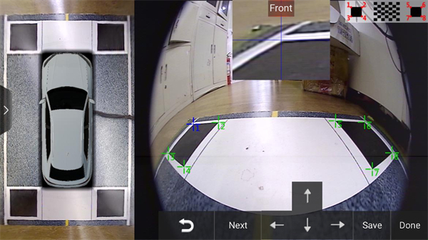
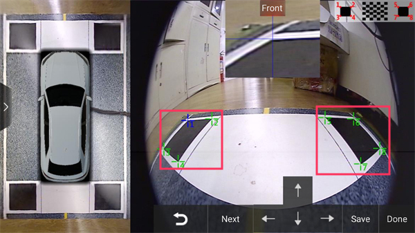
2.7.2 Manual Stitching (Key Point Calibration)
- Interface Operation: Click the "Front View", "Rear View", "Left View", "Right View" partitions on the left panoramic image to switch to the corresponding camera's calibration interface.
- Calibration Rules: Each view corresponds to 8 calibration key points, which need to be adjusted as follows:
- Drag key points: Directly drag the key point icons in the interface to adjust to the corresponding corners of the calibration cloth (such as the four corners of the large black block).
- Fine-tuning and quick movement: Short press the key point for fine-tuning (1-2 pixels), long press the key point for quick movement to the target position.
- After completing the calibration of a single view, click the "Save" button, then switch to the next view (front→rear→left→right). After all four views are calibrated, click the "Complete" button to finish the basic stitching.

Figure 10: Manual Stitching Interface
2.7.3 Common Manual Stitching Problem Adjustments
| Problem Phenomenon | Adjustment Method |
|---|---|
| Front/Rear/Left/Right images are chaotic | Reposition the key points of the calibration cloth, ensuring that the 8 points of each view accurately correspond to the corners of the calibration cloth |
| Slight deformation of front/rear image calibration cloth left/right corners | If the calibration cloth image deforms upward/downward, move the corresponding view's "coordinate points 1, 6" 1-2 pixels in the deformation direction |
| Left/right images tilt upward | Move the corresponding view's "coordinate point 5" 1-2 pixels to the left |
Before Adjustment
After Adjustment
82.8 Step 8: Post-Stitching Fine-Tuning (Resolve Image Deviation)
After stitching is completed, if problems such as image bending, non-parallelism, misalignment, or horn-shaped distortion occur, you need to enter the "Fine-Tuning Interface" (the interface will retain the fine-tuning button after stitching is completed) and adjust according to the following methods:
| Problem Type | Adjustment Function | Operation Points |
|---|---|---|
| Image bending with curvature (e.g., front view image appears curved) | Concavity/Convexity value adjustment | Drag the "Concavity/Convexity" slider, increase/decrease the value until the image returns to a straight line (front view bending adjusts the concavity/convexity value corresponding to the front view center point, same for rear/left/right views) |
| Image non-parallelism (e.g., front view image is tilted) | Displacement value adjustment | Drag the "Displacement" slider, adjust the value until the image is parallel to the vehicle body (front view non-horizontal adjusts the displacement value corresponding to the front view center point) |
| Stitching seam misalignment (e.g., left front/right front/left rear/right rear stitching areas have fractures) | Stitching seam left/right shift | If left front stitching seam is misaligned, click the "Right Shift" button for "Left Front Stitching Seam"; if right front is misaligned, click the "Left Shift" button for "Right Front Stitching Seam" until seamless |
| Horn-shaped distortion of stitching seam (e.g., front view stitching seam appears horn-shaped) | Stitching seam left/right rotation | If left front stitching seam appears horn-shaped, click the "Right Rotation" button for "Left Front Stitching Seam"; if right front is distorted, click the "Left Rotation" button for "Right Front Stitching Seam" until normal |
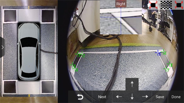
Figure 11: Fine-Tuning Interface
Note: After each fine-tuning, you must click the "Save" button to ensure the adjustment parameters take effect.
3. Core Precautions
- Tape Measure Selection: Must ensure at least 2 tape measures with length > 5m, otherwise cannot accurately measure the distance between the vehicle body and calibration cloth.
- Calibration Cloth Visibility: Front/rear cameras must see the "edge of the calibration cloth close to the vehicle direction", otherwise it will increase the blind spot.
- Camera Installation: Left and right camera angles need to be consistent, images parallel to the vehicle body, avoid stitching misalignment due to installation deviation.
- Parameter Accuracy: Vehicle parameters (such as vehicle length, width, camera height) need to be actually measured, cannot be estimated, otherwise it will seriously affect stitching accuracy.
- Lens Selection Stitching: Lens model must completely match the actually installed camera, model error will cause stitching failure.
- Fine-Tuning Save: Must click "Save" after all fine-tuning operations, otherwise adjustment content will be lost.
4. Troubleshooting (Basic)
| Fault Phenomenon | Possible Causes | Solution |
|---|---|---|
| Automatic stitching cannot recognize calibration cloth | 1. Calibration cloth not perpendicular to vehicle body; 2. Camera cannot see calibration cloth edge; 3. Light too dim | 1. Reposition calibration cloth, ensure parallel; 2. Adjust calibration cloth distance, let camera see edge; 3. Increase ambient light |
| Obvious misalignment after stitching | 1. Vehicle parameters filled incorrectly; 2. Calibration cloth key point positioning inaccurate | 1. Remeasure and correct vehicle parameters; 2. Enter manual stitching interface, recalibrate key points |
| Left/right image tilt inconsistent | Left/right camera installation angle deviation | Adjust left/right camera angles, ensure consistency, then re-stitch |